Smart Traffic light control system
Introduction
Traffic congestion and the efficient management of traffic flow are critical issues in modern urban areas. The implementation of smart traffic light control systems can significantly alleviate these problems by optimizing traffic signal timings based on real-time conditions. This project aims to develop a smart traffic light control system that can operate both automatically and manually, using a NodeMCU microcontroller. The system uses multiple switches to toggle between automatic and manual modes, allowing for flexibility in traffic management.
Objectives
Develop a Functional Traffic Light System: To create a traffic light system that can control traffic lights at three intersections.
Implement Dual Mode Operation: To enable the system to switch between automatic and manual modes using external switches.
Optimize Traffic Flow: To reduce traffic congestion by optimizing signal timings in automatic mode.
Provide Manual Override: To allow for manual control of traffic lights during special situations or emergencies.
Problem Statement
Conventional traffic light systems operate on fixed timings, regardless of real-time traffic conditions. This often leads to inefficient traffic flow, increased congestion, and longer wait times for vehicles. There is a need for a smart traffic light control system that can adapt to real-time traffic conditions and provide the flexibility of manual control when necessary.
Project Methodology
1. Component Selection and Procurement
NodeMCU (ESP8266): The core microcontroller for controlling the system.
LEDs: Representing red, yellow, and green traffic lights for three intersections.
Switches: For toggling between automatic and manual modes.
Resistors: For current limiting to protect the LEDs.
2. System Design
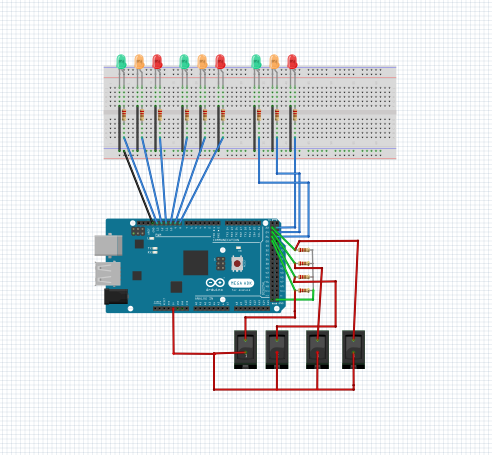
Circuit Design: Connecting the NodeMCU with LEDs and switches. Ensuring correct pin configurations for input and output operations.
Mode Selection Logic: Implementing logic to toggle between automatic and manual modes based on switch inputs.
Circuit Diagram
3. Software Development
Programming: Writing code to control the traffic light sequences in automatic mode and allowing manual override via switches.
Testing and Debugging: Ensuring the code works correctly and the transitions between light states are smooth.
The app can be available in playstore which is Blynk IOT
Code
#include <Servo.h> // Include Servo library
int switchauto = 22; // Define pin for automatic mode switch
int switch1 = 24; // Define pin for manual path1 switch
int switch2 = 26; // Define pin for manual path2 switch
int switch3 = 28; // Define pin for manual path3 switch
int switchautod; // Variable to store automatic mode switch state
int switch1d; // Variable to store manual path1 switch state
int switch2d; // Variable to store manual path2 switch state
int switch3d; // Variable to store manual path3 switch state
int r1 = 8; // Red light for path1
int y1 = 9; // Yellow light for path1
int g1 = 10; // Green light for path1
int r2 = 11; // Red light for path2
int y2 = 12; // Yellow light for path2
int g2 = 13; // Green light for path2
int r3 = 23; // Red light for path3
int y3 = 25; // Yellow light for path3
int g3 = 27; // Green light for path3
void setup()
{
Serial.begin(9600); // Initialize serial communication at 9600 baud rate
// Set pin modes for switches
pinMode(switchauto, INPUT);
pinMode(switch1, INPUT);
pinMode(switch2, INPUT);
pinMode(switch3, INPUT);
// Set pin modes for traffic lights
pinMode(r1, OUTPUT);
pinMode(y1, OUTPUT);
pinMode(g1, OUTPUT);
pinMode(r2, OUTPUT);
pinMode(y2, OUTPUT);
pinMode(g2, OUTPUT);
pinMode(r3, OUTPUT);
pinMode(y3, OUTPUT);
pinMode(g3, OUTPUT);
// Initialize all lights to HIGH (off)
digitalWrite(r1, HIGH);
digitalWrite(y1, HIGH);
digitalWrite(g1, HIGH);
digitalWrite(r2, HIGH);
digitalWrite(y2, HIGH);
digitalWrite(g2, HIGH);
digitalWrite(r3, HIGH);
digitalWrite(y3, HIGH);
digitalWrite(g3, HIGH);
}
void loop()
{
// Read switch states
switchautod = digitalRead(switchauto);
switch1d = digitalRead(switch1);
switch2d = digitalRead(switch2);
switch3d = digitalRead(switch3);
// Automatic mode
if(switchautod == HIGH && switch1d == LOW && switch2d == LOW && switch3d == LOW)
{
autoo();
}
// Manual path1
else if(switchautod == LOW && switch1d == HIGH && switch2d == LOW && switch3d == LOW)
{
path1();
}
// Manual path2
else if(switchautod == LOW && switch1d == LOW && switch2d == HIGH && switch3d == LOW)
{
path2();
}
// Manual path3
else if(switchautod == LOW && switch1d == LOW && switch2d == LOW && switch3d == HIGH)
{
path3();
}
}
// Function for automatic traffic light control
void autoo()
{
// First cycle
digitalWrite(r1, HIGH);
digitalWrite(y1, HIGH);
digitalWrite(g1, LOW);
digitalWrite(r2, LOW);
digitalWrite(y2, HIGH);
digitalWrite(g2, HIGH);
digitalWrite(r3, LOW);
digitalWrite(y3, HIGH);
digitalWrite(g3, HIGH);
delay(7000);
digitalWrite(r1, HIGH);
digitalWrite(y1, LOW);
digitalWrite(g1, HIGH);
digitalWrite(r2, HIGH);
digitalWrite(y2, LOW);
digitalWrite(g2, HIGH);
digitalWrite(r3, LOW);
digitalWrite(y3, HIGH);
digitalWrite(g3, HIGH);
delay(3000);
// Second cycle
digitalWrite(r1, LOW);
digitalWrite(y1, HIGH);
digitalWrite(g1, HIGH);
digitalWrite(r2, HIGH);
digitalWrite(y2, HIGH);
digitalWrite(g2, LOW);
digitalWrite(r3, LOW);
digitalWrite(y3, HIGH);
digitalWrite(g3, HIGH);
delay(7000);
digitalWrite(r1, LOW);
digitalWrite(y1, HIGH);
digitalWrite(g1, HIGH);
digitalWrite(r2, HIGH);
digitalWrite(y2, LOW);
digitalWrite(g2, HIGH);
digitalWrite(r3, HIGH);
digitalWrite(y3, LOW);
digitalWrite(g3, HIGH);
delay(3000);
// Third cycle
digitalWrite(r1, LOW);
digitalWrite(y1, HIGH);
digitalWrite(g1, HIGH);
digitalWrite(r2, LOW);
digitalWrite(y2, HIGH);
digitalWrite(g2, HIGH);
digitalWrite(r3, HIGH);
digitalWrite(y3, HIGH);
digitalWrite(g3, LOW);
delay(7000);
digitalWrite(r1, HIGH);
digitalWrite(y1, LOW);
digitalWrite(g1, HIGH);
digitalWrite(r2, LOW);
digitalWrite(y2, HIGH);
digitalWrite(g2, HIGH);
digitalWrite(r3, HIGH);
digitalWrite(y3, LOW);
digitalWrite(g3, HIGH);
delay(3000);
}
// Function for manual path1 control
void path1()
{
digitalWrite(r1, HIGH);
digitalWrite(y1, HIGH);
digitalWrite(g1, LOW);
digitalWrite(r2, LOW);
digitalWrite(y2, HIGH);
digitalWrite(g2, HIGH);
digitalWrite(r3, LOW);
digitalWrite(y3, HIGH);
digitalWrite(g3, HIGH);
}
// Function for manual path2 control
void path2()
{
digitalWrite(r1, LOW);
digitalWrite(y1, HIGH);
digitalWrite(g1, HIGH);
digitalWrite(r2, HIGH);
digitalWrite(y2, HIGH);
digitalWrite(g2, LOW);
digitalWrite(r3, LOW);
digitalWrite(y3, HIGH);
digitalWrite(g3, HIGH);
}
// Function for manual path3 control
void path3()
{
digitalWrite(r1, LOW);
digitalWrite(y1, HIGH);
digitalWrite(g1, HIGH);
digitalWrite(r2, LOW);
digitalWrite(y2, HIGH);
digitalWrite(g2, HIGH);
digitalWrite(r3, HIGH);
digitalWrite(y3, HIGH);
digitalWrite(g3, LOW);
}
4. Prototyping and Testing
Breadboard Assembly: Assembling the components on a breadboard for initial testing.
Simulation: Simulating traffic conditions and testing the system in both automatic and manual modes.
Adjustments: Making necessary adjustments based on test results to ensure reliable performance.
5. Deployment
Installation: Setting up the system in a real-world environment.
Monitoring and Adjustment: Monitoring the system's performance and making further adjustments if needed.
Application
The smart traffic light control system has various applications, including:
Urban Traffic Management: Improving traffic flow and reducing congestion in cities.
Emergency Situations: Allowing manual override for emergency vehicles or during special events.
Construction Zones: Managing traffic in areas with temporary road work.
Educational Purposes: Demonstrating the principles of IoT and smart traffic systems in educational institutions.
Conclusion
This project successfully demonstrates the potential of IoT-based solutions in improving traffic management. By integrating automatic and manual control modes, the smart traffic light system enhances the flexibility and efficiency of traffic control. The successful implementation of this system highlights the benefits of smart technology in urban planning and traffic management, offering a scalable solution to reduce congestion and improve road safety.
Comments
Post a Comment