Home automation with IOT
What is the Blynk app?
The Blynk app is simply an open-source platform designed for iOS / Android devices to remotely control and view hardware. It is also designed for the Internet of Things (IoT). The dashboard can be customized in a very useful way by using various Widgets such as Buttons, Displays, Sliders included in this Blynk app. Also, this widget allows you to turn devices on / off and view sensor values. Lastly, you can view, store and visualize data through this.
Install Blynk Library in Arduino IDE
There are two ways to install Blynk Library for Arduino IDE:
Using built-in library manager in Arduino IDE
Installing Blynk library as ZIP file in Arduino IDE
1.Install Blynk Library using built-in library manager in Arduino IDE
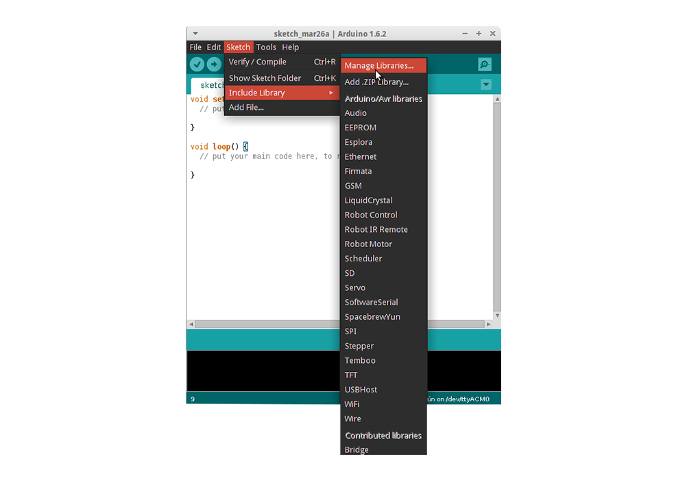
To install a new library into your Arduino IDE you can use the Library Manager (available from IDE version 1.6.2). Open the IDE and click to the "Sketch" menu and then Include Library > Manage Libraries.
Then the Library Manager will open and you will find a list of libraries that are already installed or ready for installation. Search for Blynk library and in the version selection choose the latest version to date
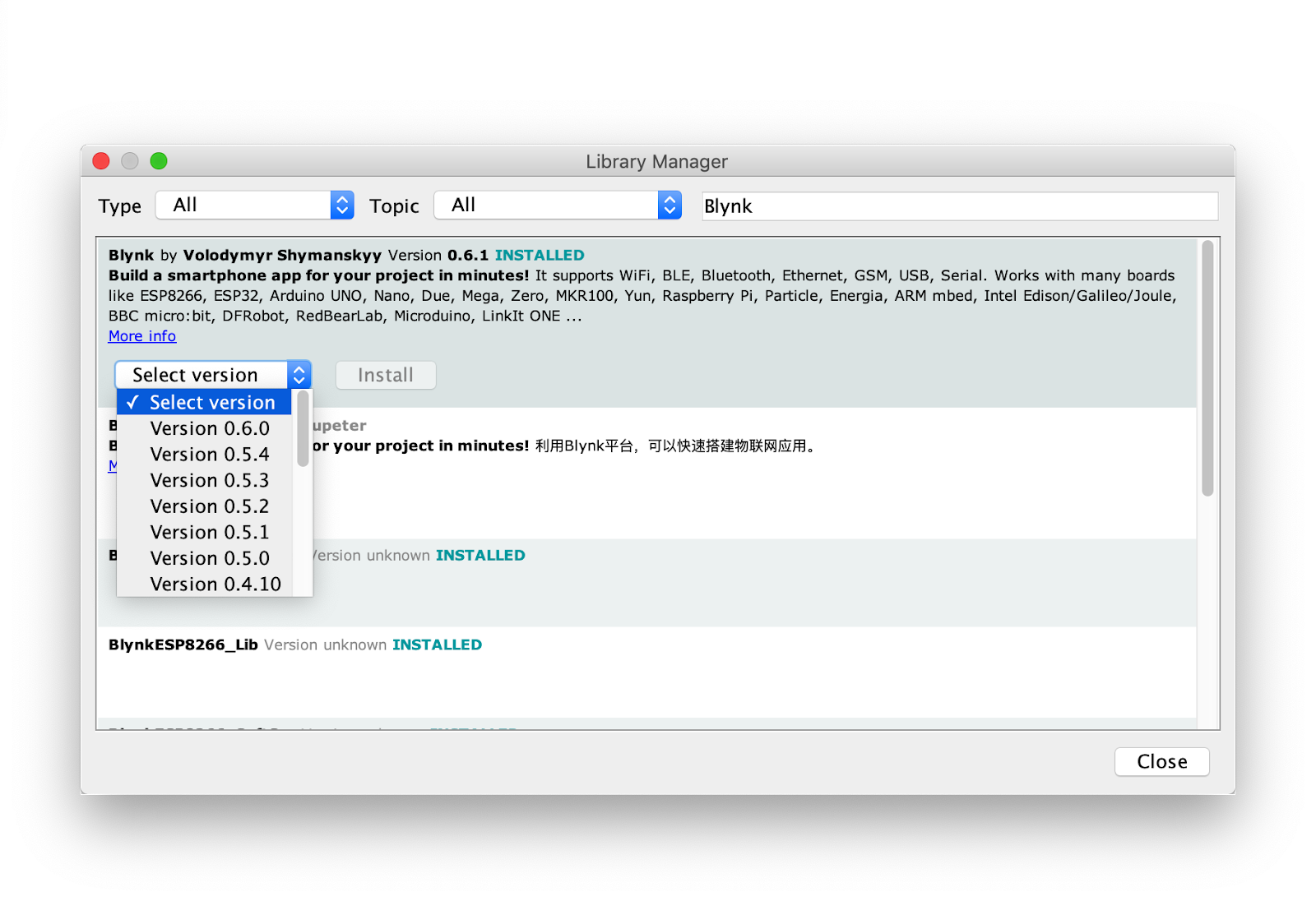
Finally click on Install and wait for the IDE to install the new library. Downloading may take time depending on your connection speed. Once it has finished, an Installed tag should appear next to the Bridge library. You can close the library manager.
You can now find the new library available in the Sketch > Include Library menu.
2. Install Blynk as ZIP file in Arduino IDE
Blynk library is available as a downloadable ZIP. Starting with Arduino IDE version 1.0.5, you can install 3rd party libraries in the IDE.
Download Blynk Library by clicking the button: Download Blynk Library
**Do not unzip the downloaded library, leave it as is.
In the Arduino IDE, navigate to Sketch > Include Library > Add .ZIP Library.
At the top of the drop down list, select the option to "Add .ZIP Library''.
Return to the Sketch > Include Library menu. menu. You should now see the library at the bottom of the drop-down menu. It is ready to be used in your sketch. The zip file will have been expanded in the libraries folder in your Arduino sketches directory.
The Library will be available to use in sketches, but with older IDE versions examples for the library will not be exposed in the File > Examples until after the IDE has restarted.
Sign Up
Open your computer browser.
Search blynk.cloud in the search bar.
Then sign up with a new account with your mail.
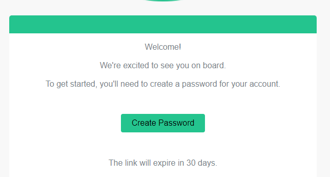
Then verify your account on your gmail.
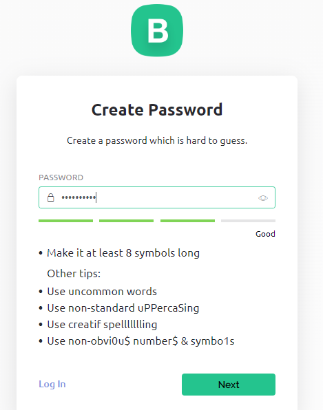
Then click on the create password and give your own password and remind it for next time sign in. Then click on Next.
Now click on skip.
Then click on the cancel button.
Your account is successfully completed.
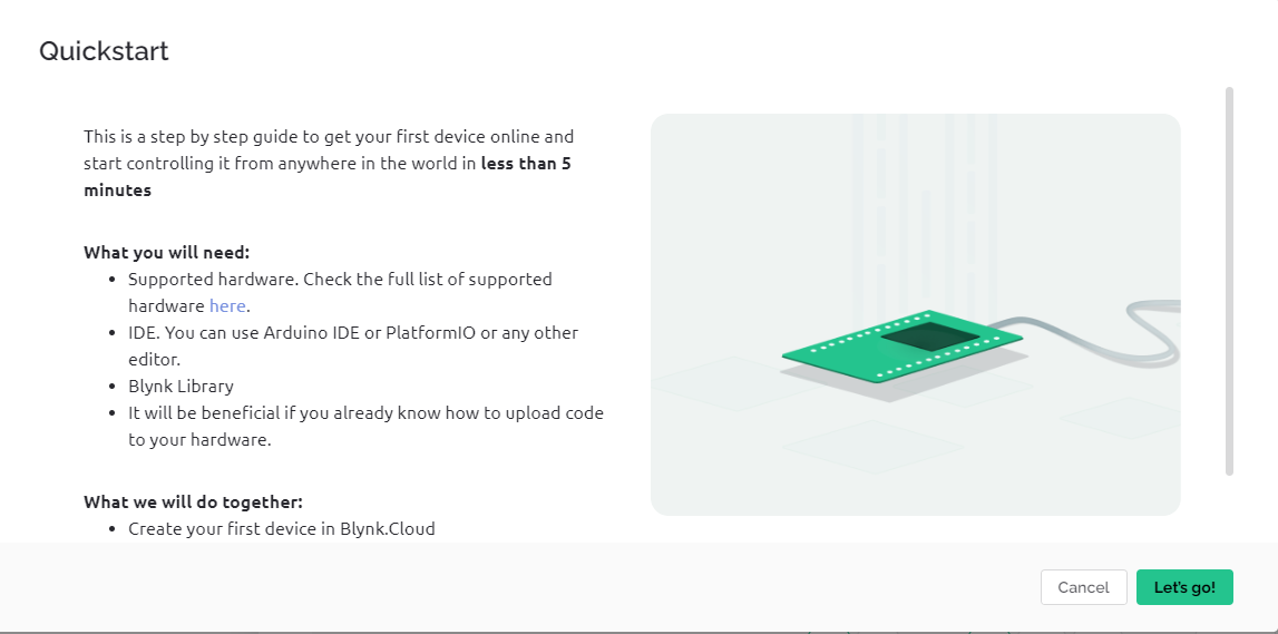
LED turn on/off using blynk cloud and your mobile phone on the NODEMCU
Go to blynk cloud website and login your blynk account. Then follow the following process.
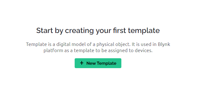
Now click on the Template as shown in figure.
Then click on the “New Template”.
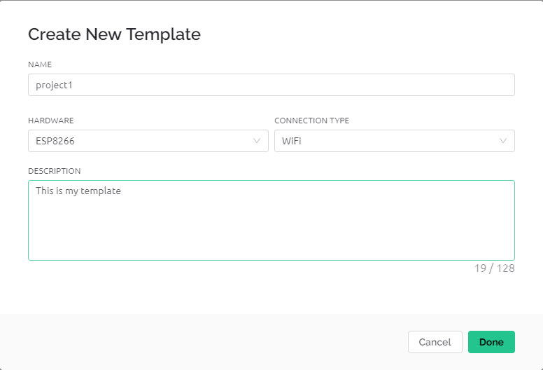
Now give your template name of project name and change the hardware into ESP8266 or ESP32 also work for NodeMCU ESP8266. Or you can describe also in description box. Then click on the ‘Done’ button.
(******Dear all, we will recommend only ESP8266 for this and further projects. So here the described method is shown for only ESP8266.)
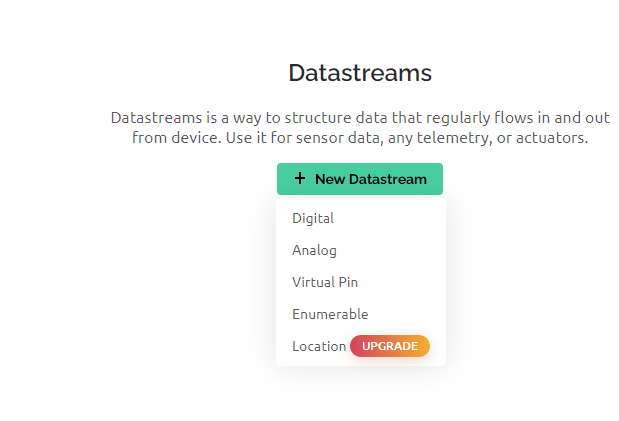
Now go to the Datastream section and click on New datastream to create a medium between to pass the data. Then choose a virtual pin and select it.
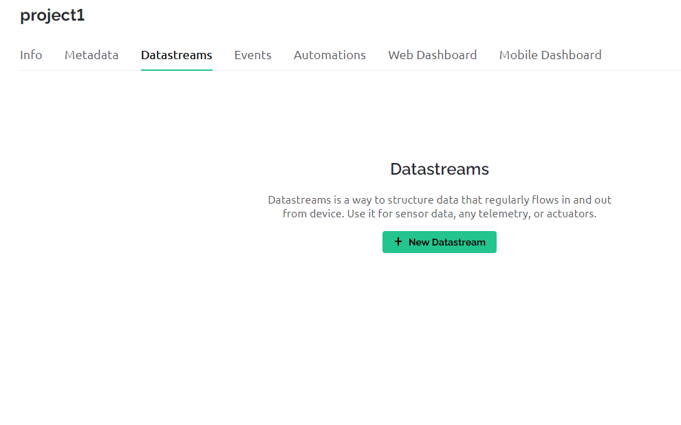
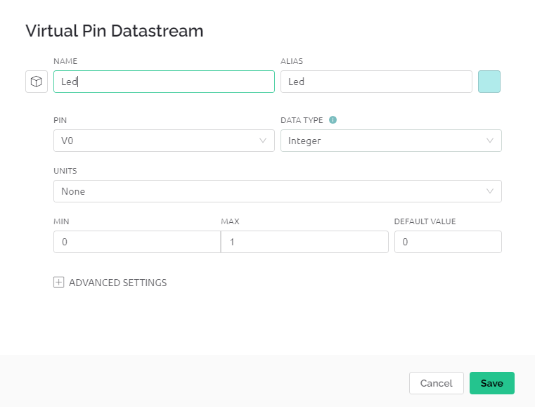
Then change the name and pin to choose any you want. Data type as it is. Units can be changed as you want(i.e for distance it could be meter). Min and Max value refer to minimum and Maximum value. To turn on or off light it will be 0 and 1 respectively. But for an example if you want to show temperature it could be from 0 10 100. Then save it.
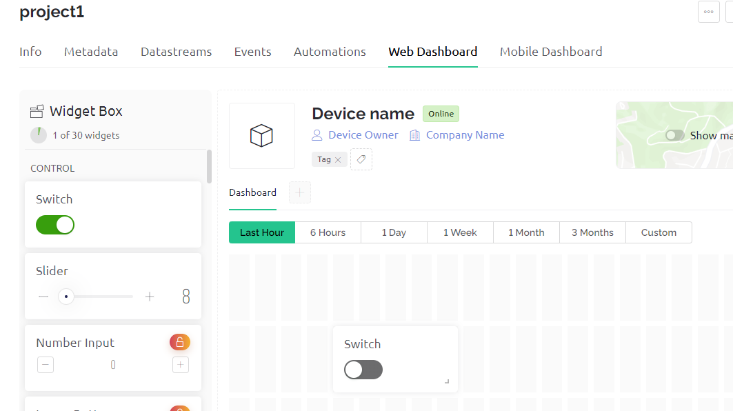
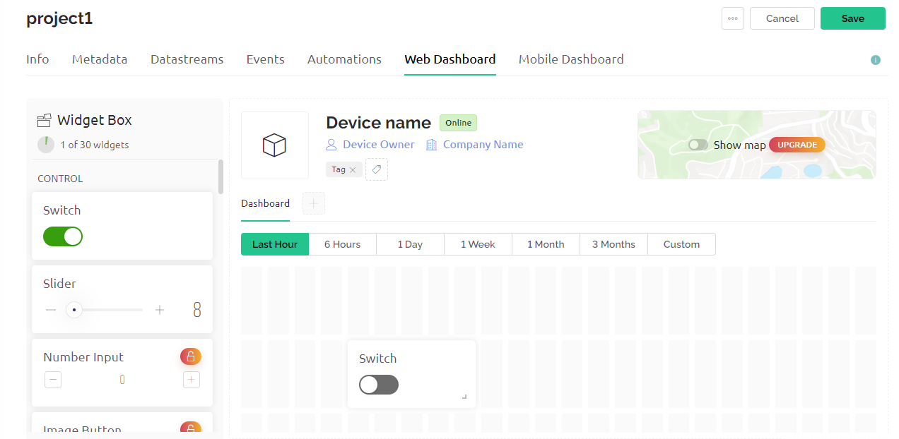
Now go to the web dashboard section. And drag the switch button to turn on and off light. But to monitor the sensor data or any data you can choose gauge and to receive and send text you can choose terminal. For the present time we will choose a switch. Then save it.
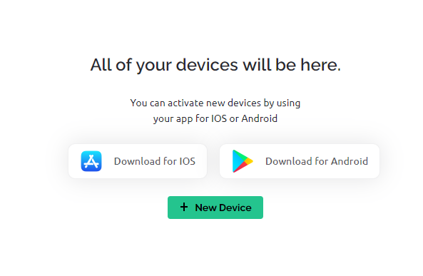
Now click on the search button as shown below.
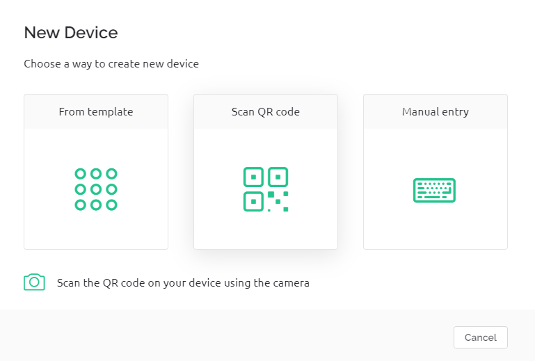
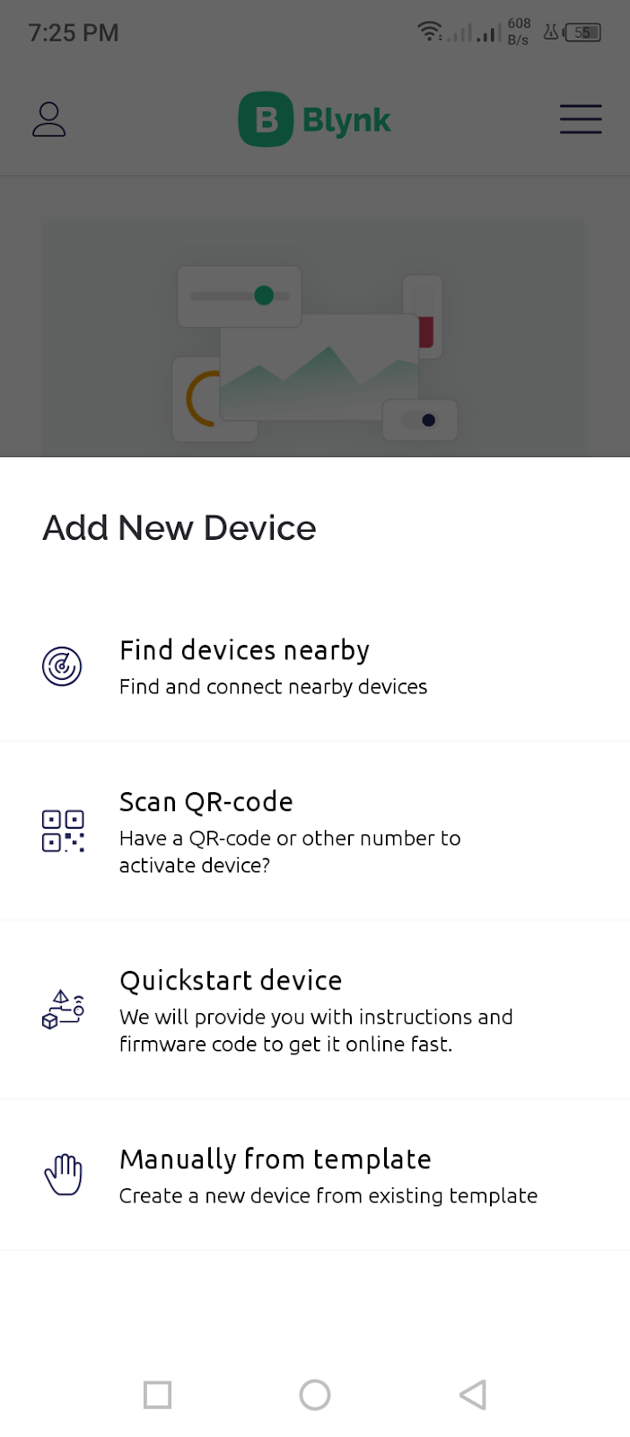
Then click on New Device.
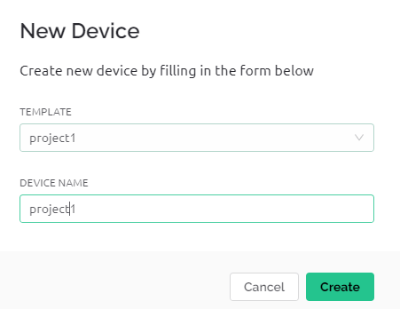
Then click on ” From Template”. And choose the template name and device name as you created before. Then click on create.
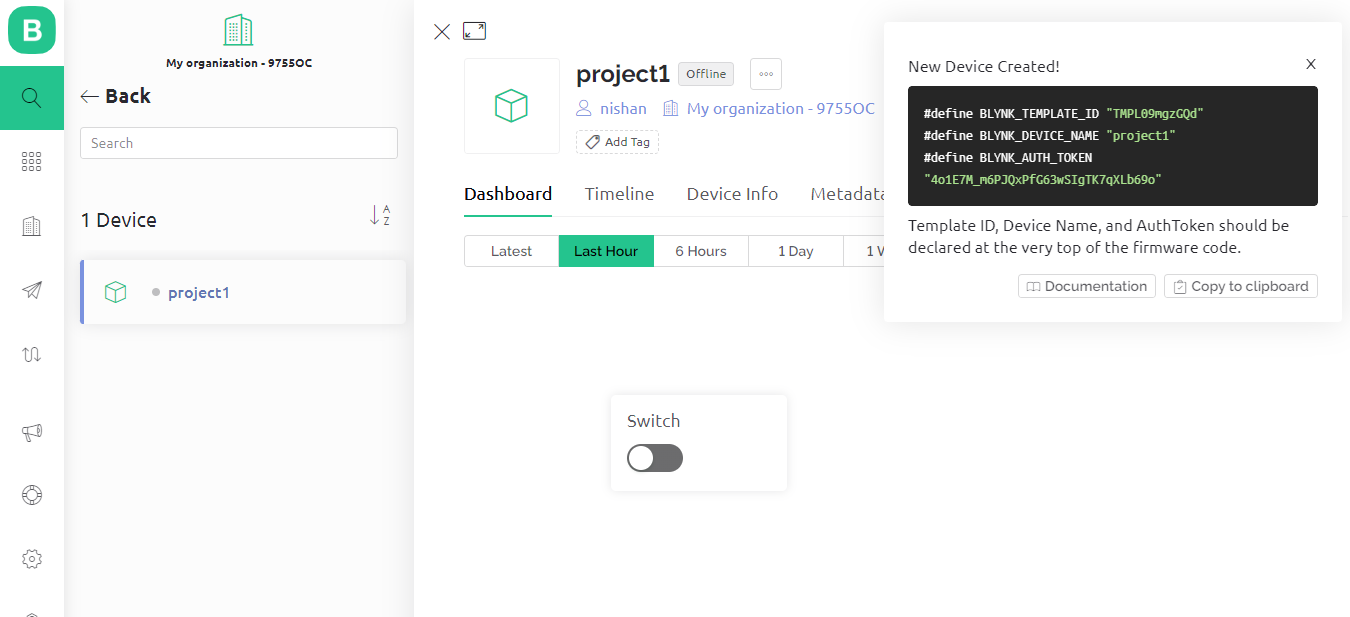
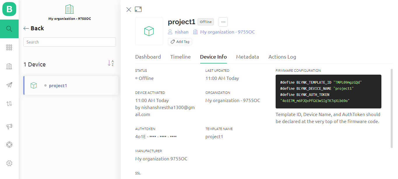
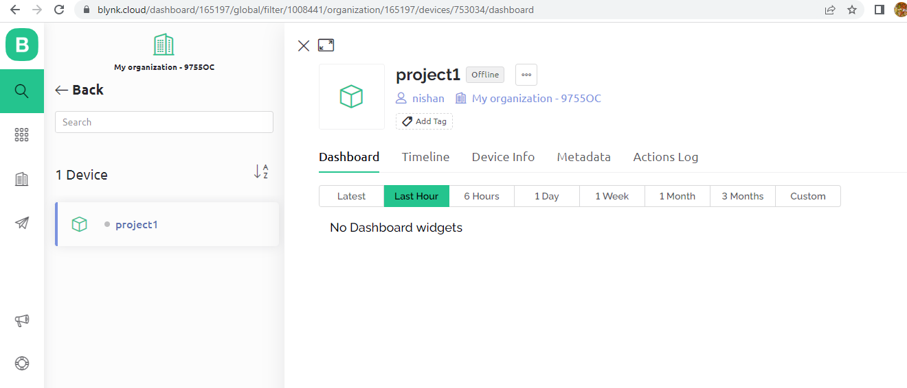
Now your dashboard will look like below. And remind that from this section you need template id, device name and auth token as shown below if right side with black background. Or this can be seen from device info also.
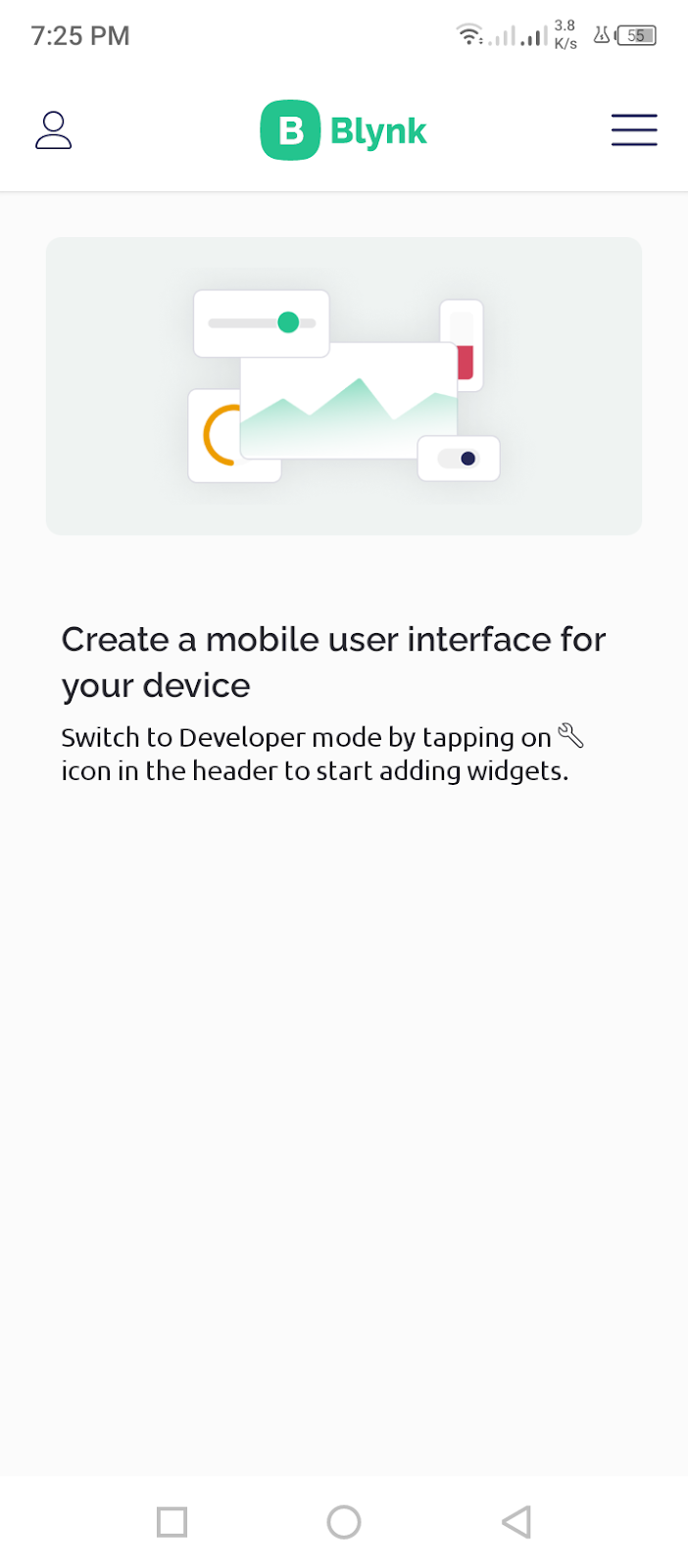
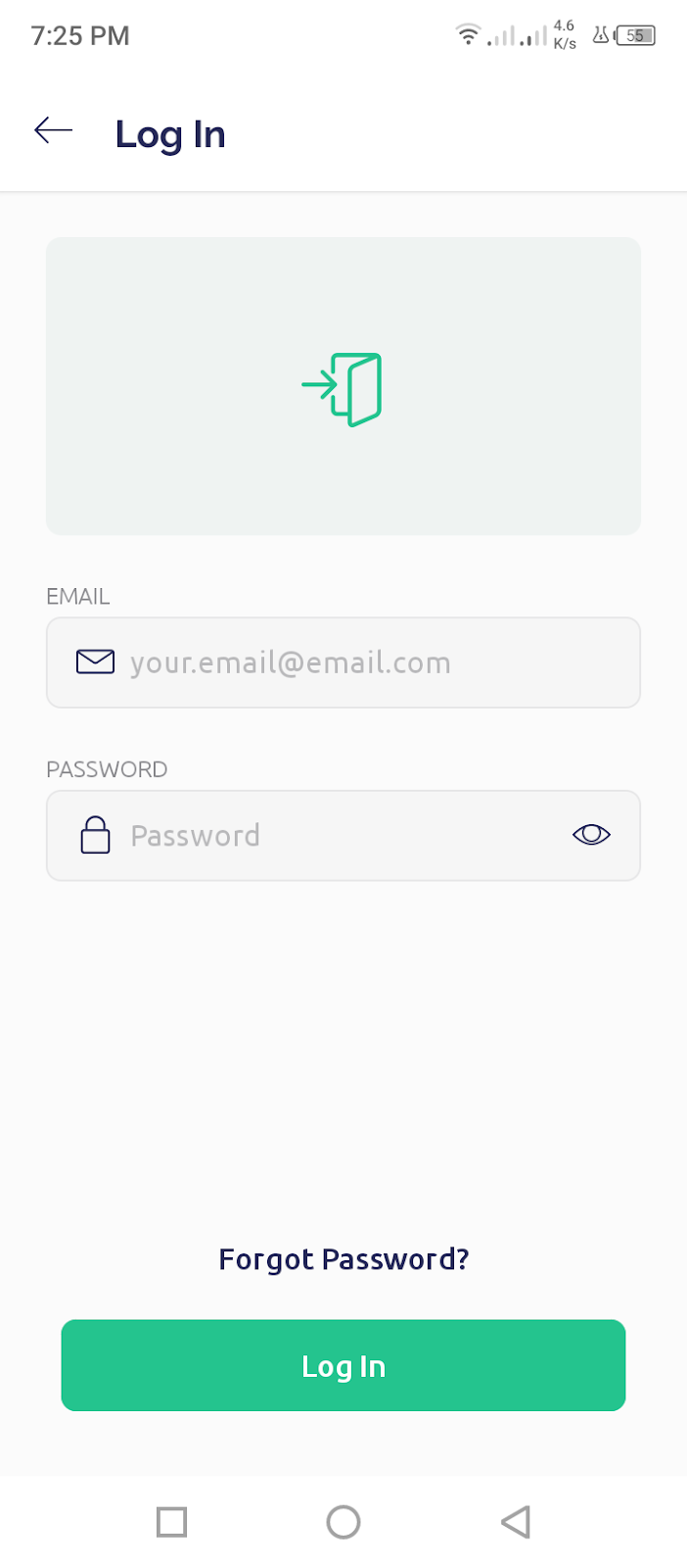
For mobile app:
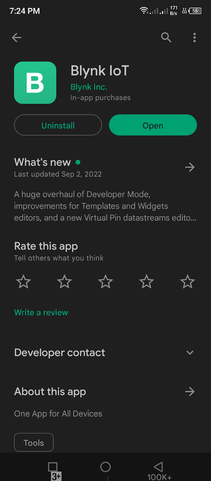
Download the mobile app named as BLYNK IOT from play store and install it.
Test your blynk and nodemcu using a simple code.
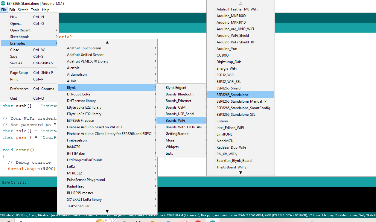
Go to your arduino IDE and open the example as below.
Files>Examples>Blynk>Boards_Wifi>ESP8266_Standalone
You can copy this code and paste it.
#define BLYNK_PRINT Serial
/* Fill-in your Template ID (only if using Blynk.Cloud) */
//#define BLYNK_TEMPLATE_ID "YourTemplateID"
#include <ESP8266WiFi.h>
#include <BlynkSimpleEsp8266.h>
// You should get Auth Token in the Blynk App.
// Go to the Project Settings (nut icon).
char auth[] = "YourAuthToken";
// Your WiFi credentials.
// Set password to "" for open networks.
char ssid[] = "YourNetworkName";
char pass[] = "YourPassword";
void setup()
{
// Debug console
Serial.begin(9600);
Blynk.begin(auth, ssid, pass);
}
void loop()
{
Blynk.run();
}
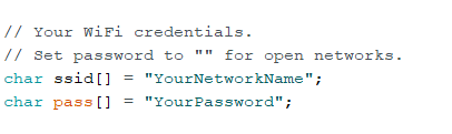
2.Then change the auth token, ssid password as follows:
3. Change the SSID (Wifi name) and password also.
**if there is a process to login for wifi access then you should not use such type of wifi. You can use either laptop hotspot or mobile hotspot but the hotspot should not be in 5GHz . It means it must be in 2GHz.**
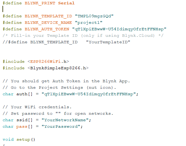
The code will be like this after changing your template id and ssid name password.
#define BLYNK_PRINT Serial
#define BLYNK_TEMPLATE_ID "TMPL09mgzGQd"
#define BLYNK_DEVICE_NAME "project1"
#define BLYNK_AUTH_TOKEN "qT1XpiEBwwW-U54IdimqyOfrEtFFNHsp"
/* Fill-in your Template ID (only if using Blynk.Cloud) */
//#define BLYNK_TEMPLATE_ID "YourTemplateID"
#include <ESP8266WiFi.h>
#include <BlynkSimpleEsp8266.h>
// You should get Auth Token in the Blynk App.
// Go to the Project Settings (nut icon).
char auth[] = "qT1XpiEBwwW-U54IdimqyOfrEtFFNHsp";
// Your WiFi credentials.
// Set password to "" for open networks.
char ssid[] = "YourNetworkName";
char pass[] = "YourPassword";
void setup()
{
// Debug console
Serial.begin(9600);
Blynk.begin(auth, ssid, pass);
}
void loop()
{
Blynk.run();
}
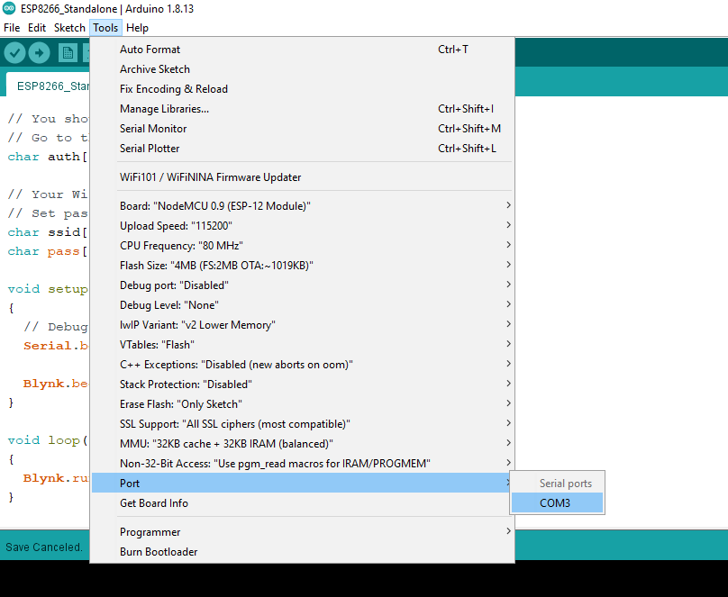
4. Now upload it after choosing the port and go to your blynk dashboard. You will see there online in your search button
Before uploading code
After uploading code you will see online.
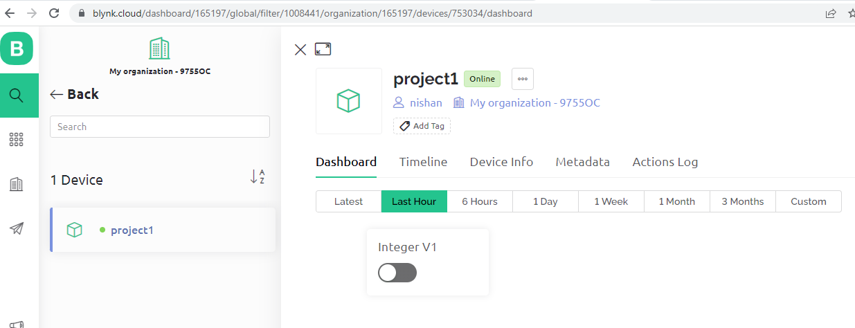
Now lets try lo control led from
Add the following code part in the above code.Or you can copy and paste following code but you have to change the template id and ssid name password.
Components required:
i) Breadboard
ii) NodeMCU ESP8266
iii) LED
iv) Jumper wires
v) 10 Kohm resistor
vi) Type B USB cable
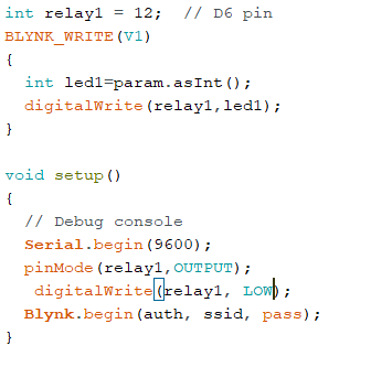
Code:
#define BLYNK_PRINT Serial
#define BLYNK_TEMPLATE_ID "TMPL09mgzGQd"
#define BLYNK_DEVICE_NAME "project1"
#define BLYNK_AUTH_TOKEN "qT1XpiEBwwW-U54IdimqyOfrEtFFNHsp"
#include <ESP8266WiFi.h>
#include <BlynkSimpleEsp8266.h>
char auth[] = "qT1XpiEBwwW-U54IdimqyOfrEtFFNHsp";
// Your WiFi credentials.
// Set password to "" for open networks.
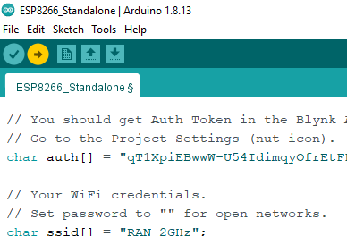
char ssid[] = "RAN-2GHz";
char pass[] = "PR4B1DH1-2";
int relay1 = 12; // D6 pin
BLYNK_WRITE(V1)
{
int led1=param.asInt();
digitalWrite(relay1,led1);
}
void setup()
{
// Debug console
Serial.begin(9600);
pinMode(relay1,OUTPUT);
digitalWrite(relay1, LOW);
Blynk.begin(auth, ssid, pass);
}
void loop()
{
Blynk.run();
}
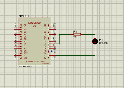
Circuit Diagram:
Now check by turning off the switch from your computer’s dashboard. Then also check from mobile app.
Now to turn off and on your AC bulb
The code and the blynk dashboard are the same till now. We will change only the circuit diagram.
The circuit diagram is shown below:
Components required:
Single channel relay module
2 pin
9 W LED bulb
AC wire
Bulb holder
Breadboard
ESP8266
Type USB cable
Jumper wire
Circuit diagram:
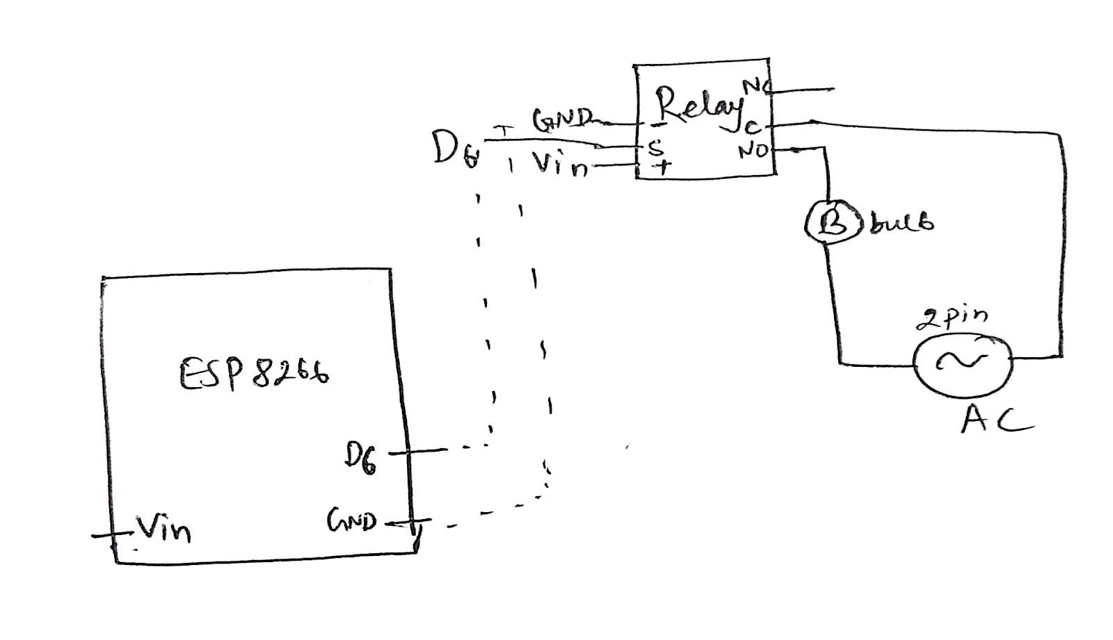
Warning
Don't touch the relay after connecting the AC supply otherwise you will be shocked.
If you use two channel relay then you have to change code format. In setup, initially you have to give HIGH because the two channel relay is active in LOW. Then in the dashboard while you choose the virtual pin then minimum value 1 and maximum value 0. Then the circuit works properly. Similarly another part is that you have to supply external DC voltage greater than 5v and less than 12 volt to run 2 channel relay. Because the power source from nodemcu is not sufficient to run the relay.
Comments
Post a Comment